
Views: 3652 Author: Site Editor Publish Time: 2026-11-19 Origin: Site

Entrapment is the one hazard in playground equipment that the standard tests with physical probes rather than with calculation, and a buyer who has never seen Annex D of EN 1176-1 usually assumes the gap rules are simple numbers. They are not. The standard defines six test tools, applies a different one to each body part, and in most cases expresses the requirement as a pass condition on the probe rather than as a dimension: a completely bounded opening is acceptable if the torso probe cannot pass, or if the torso probe and the small head probe can pass but the large head probe cannot. This guide walks through the six probes and what each one is for, the head and neck rules including the 600 millimetre height threshold and the 230 millimetre suspended bridge limit, the finger rules built on the 8 millimetre and 25 millimetre rods, the clothing and hair toggle test, the foot and leg rules and the 30 millimetre limit, the extra rules that apply to moving and suspended equipment, how the European probes differ from the North American ones, and which documents a buyer should hold before the equipment opens to the public.
1. Why Entrapment Is Tested with Probes and Not with a Table of Gaps
2. The Six Test Probes in Annex D and What Each One Represents
3. Head and Neck Entrapment: The Rules That Catch Most Buyers Out
4. Finger Entrapment: The 8 Millimetre and 25 Millimetre Rod Logic
5. Clothing and Hair Entrapment: The Toggle Test
6. Foot and Leg Entrapment and the 30 Millimetre Limit
7. Whole Body Entrapment and the Moving Equipment Rules
8. How the European Probes Differ from the North American Ones
9. Entrapment in GRP, Steel and Rope: Where the Gaps Actually Appear
10. Common Mistakes to Avoid
11. What to Ask a Supplier and What to Hold on File
12. Frequently Asked Questions
13. Buyer Checklist
14. Final Thoughts

The reason the standard does not publish a single list of permitted gaps is that a gap on its own does not describe the hazard. The same 120 millimetre opening is a hazard in one position and harmless in another, and the variables are the orientation of the child, the direction of movement, whether the opening changes shape in use, and how far the child can reach. A probe-based test measures the combination instead of the dimension. The tool is pushed into the opening in the direction a child's body would travel, and the standard then states the condition under which that outcome is acceptable.
This matters commercially as well as technically. A supplier who quotes a single safe gap figure is quoting something the standard does not contain, and a buyer who accepts that figure has no way to check it. A supplier who instead references the Annex D probe set and the corresponding clause can be checked against the delivered equipment, because the same tools can be applied to the product in the workshop and again by an inspector on site. The second approach is what turns an assurance into a verifiable claim.
Annex D of EN 1176-1 defines six test tools, and the standard uses them as a set rather than individually. The torso probe represents a child's trunk and is used to establish whether an opening is large enough for the body to pass through. The large head probe, which is a 230 millimetre template, represents the head of an older child. The small head probe represents the head of a younger child and is the tool that decides the partial entrapment cases. The wedge probe is a flat, tapered template used for the fish-shaped and V-shaped opening geometry. The two finger rods are plain cylindrical rods of 8 millimetres and 25 millimetres diameter, used for the finger rules.
Two further devices complete the set for the clothing and hair cases: a toggle test device for the drawstring and toggle entrapment check, and a ring gauge used to test for hazardous projections on rocker hand and foot rests. The important point for a buyer is that the probe set is a defined set of physical tools with fixed dimensions, not a set of judgment calls. When a test report states which probes were applied to which clause, and gives the result for each, it can be compared against another report for the same standard without any translation.
| Test tool | Body part represented | Clause applied | Acceptance condition in short |
|---|---|---|---|
| Torso probe | Child trunk | 4.2.7.2 head and neck | Must not pass a completely bounded opening above 600 mm unless the large head probe also passes |
| Large head probe | Head of an older child, 230 mm template | 4.2.7.2 head and neck | Passing this probe releases the head, which is the condition that makes a bounded opening acceptable |
| Small head probe | Head of a younger child | 4.2.7.2 head and neck | Must not pass alongside the torso probe, in the same way as the torso probe |
| Wedge probe and fish-shaped template | Partially bounded and V-shaped openings | 4.2.7.2 b) with method D.2.2 | Applied where the entry to the opening is 600 mm or more above the ground |
| Finger rod, 8 mm | Child finger | 4.2.7.6 finger entrapment | Must not pass the minimum cross-section of the opening, and must not be able to lock in it |
| Finger rod, 25 mm | Child hand | 4.2.7.6 finger entrapment | Where the 8 mm rod passes, the 25 mm rod must also pass, provided no other finger site is reachable |
| Toggle test device | Drawstring and clothing toggle | 4.2.7.3 clothing and hair | Applied to slides, sliding poles and roofs, where the user is in forced movement |
| Ring gauge | Rocker hand and foot rest projections | 4.2.7.3 and the general protrusion rules | Checks that a projection is not shaped so as to catch a drawstring |
Clause 4.2.7.2 requires that equipment be constructed so that no opening creates a head or neck entrapment hazard, whether the child passes through head first or feet first. For a completely bounded opening whose lower edge sits more than 600 millimetres above the play surface, the acceptance condition is that the torso probe and the small head probe must not pass through, unless the opening also allows the passage of the large head probe. In plain terms, an opening that lets the body part through but traps the head is the failure case, and an opening that either stops the body or releases the whole head is the pass case.
The 600 millimetre threshold is where most mistakes happen, and it is applied to the lower edge of the opening, not to the centre of it and not to the height of the platform as a whole. It matters because openings at platform level are generally below the threshold and are assessed against the body and leg rules instead. It also means that a fence panel, a handrail infill or a balustrade can fall under the head rules even though the operator thinks of it as a barrier rather than as a climbing feature.
Partially bounded and V-shaped openings are treated separately. Where the entry to such an opening is 600 millimetres or more above the ground, the standard directs the use of the fish-shaped template in the wedge probe method under D.2.2. A second V-shaped rule applies to the free area and to the space in front of it, where a V-shaped opening with an included angle below 60 degrees is treated as a hair and clothing hazard. And where flexible elements such as ropes overlap each other, the standard requires that they do not combine into an opening that would fail the completely bounded rule, which is a check that cannot be made on a drawing at all because rope positions change under load.
One further limit is worth naming because it appears on almost every swing and bridge structure. The gap between the flexible part of a suspension bridge and any rigid lateral part must be at least 230 millimetres in diameter under the most unfavourable load condition, and both the loaded and the unloaded situation are considered. On a swing set this is the gap between the seat chains and the frame, and on a rope bridge it is the gap between the deck and the side rail. It is a single number and it is easy to check with a rule at handover.
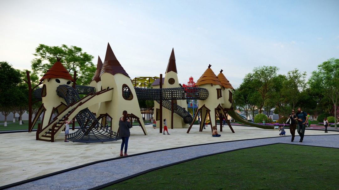
Clause 4.2.7.6 handles the finger case, and it is the part of the standard most often summarised incorrectly. The rule applies to openings in the free space where the user is subjected to forced movement, and to holes whose lower edge is more than 1,000 millimetres above the potential impact area. The first condition is that the 8 millimetre finger rod must not pass through the minimum cross-section of the opening, and the profile of the opening must be such that the rod cannot be locked into any position when the opening is set in motion. The second condition applies where the 8 millimetre rod does pass: in that case the 25 millimetre rod must also pass through, provided the opening does not give access to another finger entrapment site.
The logic behind this is worth understanding, because it is not a gap table. A narrow gap that a finger can enter but that the hand cannot follow is the amputation risk, because a child pulling or sliding applies a force the finger cannot resist. A wide gap that the whole hand passes through is not a finger trap, because the hand travels with the child. The two rods encode the difference, and a gap that passes one rod but not the other is the exact condition the clause rejects.
Two further provisions close the most common loopholes. The ends of tubes and pipes must be closed off to prevent finger entrapment risk, and the closures must not be removable without using tools, which is the same principle that governs accessible fasteners. And where the dimension of a gap changes during use of the equipment, the gap must have a minimum dimension of 12 millimetres in any position, which is a dynamic requirement that a static drawing cannot satisfy.
Clause 4.2.7.3 deals with the situation where a drawstring, a shoelace or a piece of hair is caught in a gap, a protrusion or a rotating part, and the child is then dragged or held. The standard applies the requirement to slides, sliding poles and roofs, because these are the positions where the user is subject to forced movement with no hand or foot support available. The standard deliberately does not apply the toggle test to climbing walls, on the reasoning that a climber has a number of hand and foot holds within reach at any one time and therefore more opportunity to control the movement.
For a buyer, the practical consequence is that the toggle test applies exactly where a child sits down and slides, which is where the incidents occur. A report that records the toggle test result for the slide, the sliding pole and the roof is therefore a report that covers the highest-risk geometry on the product. A report that records only the structural load test does not, however well it is written, and the two are often confused because both appear under the same type examination number.
Clause 4.2.7.5 covers entrapment of the foot and the leg, which happens most often on the running and climbing surfaces where a child's foot enters a gap while the body keeps moving. The requirement for surfaces intended for running and walking is that gaps in the main direction of travel must not be greater than 30 millimetres, and the standard sets a corresponding limit across the direction of travel. For inclined planes other than suspension bridges, where the slope is less than 38 degrees, there must be no gaps over 30 millimetres.
This is the rule that a buyer can verify fastest, because a 30 millimetre gap can be checked with a rule and a wedge on site in minutes. It is also the rule most often breached by a late change, such as a decorative panel added after the main structure was approved, or a footrest bracket relocated to clear a drainage problem. Any such change should be re-checked against the 30 millimetre limit and against the head rules above it, because the same opening can be more than 600 millimetres above the surface in one position and below it in another.
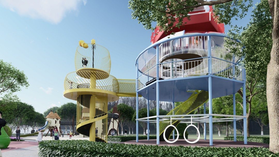
Clause 4.2.7.4 addresses whole body entrapment, and it has two parts. Equipment must be constructed so that there are no tunnels into which children can crawl with their whole body, and no suspended parts that are heavy or have rigid suspension. A crawl tunnel is judged on whether the child can enter it, so a tunnel that is attractive to a small child and just wide enough for them is a failure even though it is perfectly safe for an adult to walk through.
The suspended equipment rules add a separate set of dimensional duties for heavy suspended rigid beams, defined as a mass of 25 kilograms or more. The ground clearance below such a beam must be at least 400 millimetres, measured from the lowest point of the lower edge of the beam to the underlying surface. Every variation in the beam profile must have a radius of at least 50 millimetres. The range of movement must not be greater than 300 millimetres and must not extend beyond the support uprights. The distance between the support uprights and the heavy suspended rigid beam must not be less than 230 millimetres throughout its entire range of movement.
These numbers matter most for the equipment that moves under the child, because the hazard is created by the combination of a heavy element and a moving one. A buyer who is comparing a swing bay, a rocker or a suspended platform should check the 400 millimetre clearance and the 230 millimetre separation directly on the delivered product, and should confirm that the movement range was measured rather than assumed.
A project that has to satisfy more than one market needs to know where the two systems differ, because the tooling is not interchangeable. The North American system under ASTM F1487 uses a 3.5 inch torso template, which is 89 millimetres, and a 9 inch head template, which is 228.6 millimetres, and it applies a different partial neck entrapment geometry with a 55 degree angle and a 19 millimetre thickness probe, while the European system uses a 45 degree and 30 degree angle with a 45 millimetre thick probe for the equivalent case. The clothing entrapment test differs as well, with the North American approach using a 3 millimetre square rod tester against a chain type test device in Europe.
The practical effect for a manufacturer that wants one product for both markets is that the more restrictive of the two limits governs every opening, because a design that passes the tighter geometry passes the looser one by construction. That is a design decision taken once and it costs nothing later, which is why dual certification is worth pursuing at the drawing stage rather than at the test stage. ISO/TR 24666, which collects the probe data from the European, North American and Asian systems, is a useful reference when reconciling the three sets of tools and it also records the special probe requirements developed for children aged 6 to 23 months.
The hazard is not evenly distributed across a playground, and knowing where it concentrates makes the inspection faster. On steel equipment it is the openings in the platform panels, the gaps between a handrail and the platform edge, and the transitions where a slide meets a platform. On moulded components it is the openings formed between a moulded shell and a steel frame, and the shaped cut-outs in a climbing panel. On rope and net structures it is the gaps between the rope and the frame at every connection, plus the small openings produced where two ropes cross, which is why the standard requires that overlapping flexible elements must not create a failing opening.
Moulded parts deserve a specific note because of how they age. EN 1176-1 requires that the operator be able to visually identify excessive wear of the gelcoat of glass reinforced plastic products intended for sliding before the user becomes exposed to the glass fibres, and EN 1176-7 requires that such parts are replaced or repaired once the glass fibres become visible. A worn gelcoat changes a sharp edge into a ragged one, and a moulded opening whose rim has worn can pass a probe measurement when it was new and fail one after two seasons. A buyer should therefore ask for the wear indicator method to be part of the handover documents and should check the slide and the climbing panels at the first operational inspection rather than only at the annual main inspection.

The first mistake is treating entrapment as a gap dimension. A buyer who writes "all openings between 100 and 200 millimetres are prohibited" has written a rule that is neither the European requirement nor the North American one, and it will pass a product that fails the probe test while rejecting a product that passes it. The clause references, the probe names and the height thresholds are what make the requirement enforceable, and the thresholds are the part that gets left out.
The second mistake is using the lower edge of the opening as a fixed height rather than measuring it in the delivered configuration. The 600 millimetre and 1,000 millimetre thresholds are read from the equipment as built, which means that a step, a base frame or a fixing bracket can move an opening from one rule to the other, and a supplier who designed to the drawing may not have seen the effect of the installed height.
The third mistake is checking the products and not the spaces between them. Two products placed side by side form a gap that neither product report covers, and a swing bay installed next to a fence creates an opening that no individual item report addresses. The post installation inspection exists for this reason, and the combination needs to be assessed as an assembly.
The fourth mistake is accepting a report for a catalogue item as though it covered a custom configuration. Every additional panel, every wider span and every relocated bracket changes at least one opening dimension, and once one dimension changes the probe result for that opening has to be re-established. The fifth mistake is applying a single market standard to a project that will be inspected in two markets, when the more restrictive geometry can be adopted at the drawing stage at no cost and cannot be adopted after the product is built.
The sixth and most costly mistake is leaving the entrapment evidence out of the handover pack. The report proves what was tested on the day it was tested, and it does nothing for the operator standing in front of the slide five years later with a worn gelcoat and a question about whether the moulding is still acceptable. The handover file should contain the probe results, the inspection criteria and, for any moulded component, the wear indicator and the replacement period, so that the annual inspection has something to work from other than a memory of the original purchase.
The conversation with a supplier is more productive when it is anchored to the probe set rather than to a general request for a test report. Ask which Annex D probes were applied, to which clause of EN 1176-1, and to which product model and variant. Ask whether the result was recorded for the delivered configuration or for a catalogue item, because a panel that is 20 millimetres wider on a custom project changes the result. Ask how the 600 millimetre and 1,000 millimetre thresholds were applied, since these determine which rule applies to each opening. Ask what was done about openings formed by overlapping flexible elements and whether the position was assessed under load.
On file, hold the type examination or test report for the exact model, the drawing or panel schedule that shows the opening dimensions the report was taken against, the probe results for the head, finger, clothing and foot cases, and the entrapment-related inspection criteria handed to the operator. If the project is multi-market, hold the North American report alongside the European one so that the more restrictive geometry is traceable to a decision rather than to an accident in the field. And if the equipment includes any GRP component, hold the replacement period and the wear inspection method described in the material requirements, because a moulded part is the one element where the geometry can change after the report was issued.
No. The standard expresses the requirement as pass conditions on physical test tools rather than as a table of permitted dimensions, because a gap alone does not describe the hazard. The orientation of the child, the direction of movement, the height of the opening above the play surface and the behaviour of the gap under load all change the outcome. Several individual dimensions do appear in the text, including the 600 millimetre and 1,000 millimetre height thresholds, the 230 millimetre limit at a suspended bridge, the 30 millimetre limit for foot entrapment and the 8 millimetre and 25 millimetre finger rods, but the governing test remains the probe.
Not necessarily. A report covers the product variant that was submitted, and a project combines several products whose frames, panels and connections interact. Where items are close to each other, the gap between two separate products can form an opening that neither product report addressed. The project should confirm that the combination as installed was assessed, and the post installation inspection by a competent person under EN 1176-7 is the point at which that is checked on the real site.
Yes, and it needs more than the same check, because rope positions move. The standard requires that openings whose dimension changes during use have a minimum dimension of 12 millimetres in any position, and it requires that overlapping flexible elements do not create openings that fail the completely bounded rules. A rope net is therefore assessed at its worst configuration under load rather than at its rest configuration, which is why a rope net assessment cannot be completed from a photograph.
Yes, a competent person should carry it out at handover, because EN 1176-7 requires a post installation inspection to be carried out by a competent person on completion of a new playground, to assess compliance with the relevant part of EN 1176. That inspection is a site verification of what the report covered in the workshop, and the two should agree. A buyer who has not received the report, the drawing that the report was taken against and the installation instructions cannot reasonably expect that inspection to produce anything beyond a list of items to be corrected.
First, ask which of the six Annex D probes were applied, to which clause of EN 1176-1, and to which model and variant of the equipment. Second, ask how the 600 millimetre height threshold was applied to each opening, since this decides whether the head rules or the body rules govern it. Third, ask how the 1,000 millimetre threshold was applied to the finger rules. Fourth, require the 8 millimetre and 25 millimetre rod results for every opening in the free space and for every hole whose lower edge is above 1,000 millimetres. Fifth, require the toggle test result for the slide, the sliding pole and the roof, and confirm that the assessment was made on the delivered configuration.
Sixth, require the 30 millimetre check on the running and walking surfaces in the main direction of travel and across it, and on inclined planes below 38 degrees. Seventh, check the 230 millimetre separation at the swing bays, the rope bridges and the suspended platforms, and the 400 millimetre clearance, 50 millimetre profile radius, 300 millimetre movement range and 230 millimetre upright separation for any heavy suspended rigid beam over 25 kilograms. Eighth, require evidence that overlapping rope and net elements were assessed in their loaded configuration. Ninth, require that the open ends of tubes and pipes are closed with closures that cannot be removed without tools.
Tenth, for a project sold in more than one market, hold the European and the North American reports together and confirm that the design applies the more restrictive of the two geometries. Eleventh, for any moulded GRP component, require the replacement period stated by the manufacturer and the visual wear indicator method that lets the operator see gelcoat wear before the glass fibres are exposed. Twelfth, hold the panel schedule and the drawings that the report was taken against, so that a later modification can be checked against the same dimensions. Thirteenth, arrange the post installation inspection by a competent person under EN 1176-7 before the site opens to the public, and record the entrapment findings in the handover file.
When these thirteen items are in the purchase document, the entrapment question stops being a matter of trust and becomes a matter of record. The report says which probes were used on which clause, the drawing shows the dimensions the report was taken against, and the operator inherits both the inspection criteria and the parts that will eventually need attention. That combination is what allows a public playground to be handed over, inspected annually for many years, and defended in the event of an incident, without anyone having to reconstruct what was tested and when.

Entrapment is the hazard that separates a compliant playground from a dangerous one, and it is the one that cannot be checked by looking at a photograph or by quoting a single safe gap figure. The standard was written around physical tools because the risk lives in the interaction between a body, a movement and an opening, and no dimension captures all three. Six probes, applied clause by clause, is a compact method that a competent person can repeat on site years after the equipment was delivered.
For a buyer, the practical approach is to treat the probe results as part of the product evidence rather than as a footnote to it. Ask which tools were used, ask where they were used, ask against which drawing, and keep the answers with the handover documentation. Ask the same questions of every product that shares the site, because the dangerous openings are often in the space between two products rather than inside one. And where the project has to pass inspection in more than one jurisdiction, take the more restrictive geometry at the design stage, where it is free, rather than at the test stage, where it is not.
For a supplier, the same discipline is what turns a catalogue claim into something a buyer can specify. A test report that names the probes, the clauses, the model and the configuration, paired with the panel schedule that the report was taken against, is a document set that answers the questions a project buyer will ask before the order is placed. When a supplier can produce that set for a custom configuration rather than only for a standard item, the entrapment discussion becomes a short exchange instead of an obstacle.
Send the technical requirements for the project and ask which documents will accompany the specific proposal through the NUUTOO project enquiry page, and confirm how the playground equipment, the playground surfacing and the surrounding custom playground equipment are coordinated so that the falling space and the free space stay consistent with the tested geometry.
The commercial playground manufacturer selection guide covers the wider commercial criteria for a supplier, and the entrapment evidence is one of the most useful filters within it, because a manufacturer that answers the probe question with named clauses, named tools and a named model is a manufacturer that will answer the structural and material questions in the same way.
 English